- All
- Product Name
- Product Keyword
- Product Model
- Product Summary
- Product Description
- Multi Field Search
Please Choose Your Language
Views: 0 Author: Site Editor Publish Time: 2026-07-02 Origin: Site
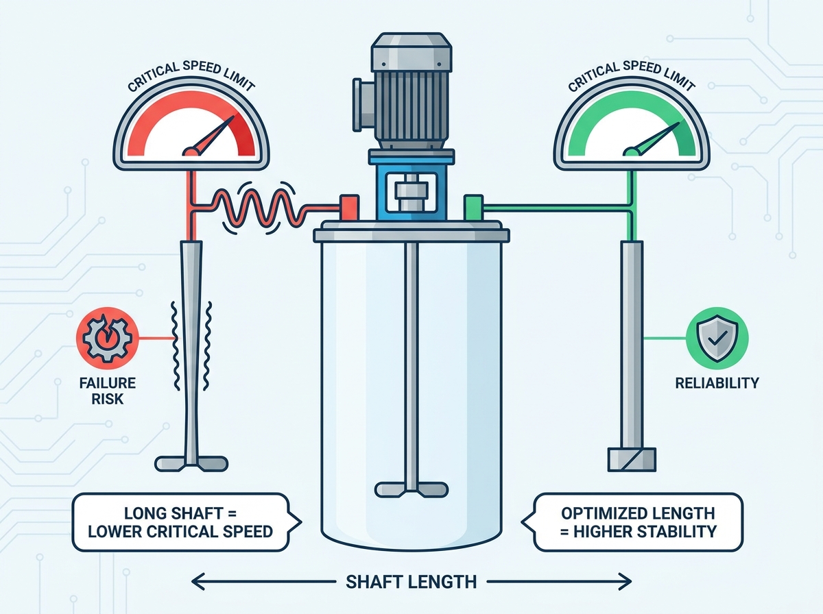
Industrial mixing relies heavily on mechanical stability to maintain continuous production. A top entry agitator operates as an overhung cantilevered load, making it inherently susceptible to severe dynamic forces. Ignoring shaft dynamics during the specification phase leads to premature mechanical seal failure, accelerated bearing wear, violent resonance bending vibration, and catastrophic shaft breakage, resulting in costly unplanned downtime. Specifying a reliable unit requires a rigorous evaluation of the relationship between shaft length, shaft diameter, impeller mass, and the system's first lateral natural frequency (critical speed). We will explore how these variables interact and dictate equipment reliability on the plant floor.
Critical Speed Margin is Non-Negotiable: Industry best practice dictates that continuous operating speed should not exceed 65% to 80% of the agitator’s first critical speed, with stricter margins (65%) applied to unsupported cantilever designs.
Length Amplifies Risk: Shaft deflection increases exponentially (cubically) with shaft length, requiring precise engineering interventions for deep-tank applications.
VFDs Require "Block-Out" Zones: Variable Frequency Drives cannot be used to safely operate near critical speed; a +/- 20% block-out speed range must be programmed to prevent violent vibration during ramp-up or ramp-down.
Vibration Begins Before Resonance: High-amplitude deflection and structural stress do not just occur at peak critical speed; they begin to escalate rapidly as the operating speed approaches the critical threshold.
Design Trade-offs Dictate Lifecycle Cost: Upgrading to thicker or hollow shafts increases upfront capital expenditure but eliminates the high maintenance risks associated with bottom steady bearings.
Every physical object possesses a natural frequency. When an impeller rotates in a tank, it generates minor unbalanced forces. These forces create harmonic excitation along the shaft. If the rotational speed matches the shaft's natural frequency, resonance occurs. This specific rotational velocity is the first lateral natural frequency. Engineers commonly call this the critical speed. At this velocity, the system loses its ability to dampen vibration. The amplitude of shaft deflection multiplies rapidly. This resonance causes violent shaking. It destroys mechanical seals and shatters gearbox bearings.
Many operators mistakenly believe danger only exists at the exact critical speed peak. This represents a dangerous misconception known as the approach hazard. High-amplitude deflection begins long before reaching the exact resonant frequency. As the operating speed approaches the critical threshold, structural stress escalates rapidly. The shaft begins to deflect aggressively from its true centerline. This deflection creates immediate radial stress on the gearbox. It places severe strain on the mounting flange. Fluid dampening begins to fail. You must account for this approach hazard during the initial design phase to prevent premature component wear.
In field applications, you can observe the approach hazard visually. A shaft running at 40% of its critical speed might show a runout of 0.05 inches at the seal. Push that same shaft to 85% of its critical speed, and the runout might jump to 0.25 inches or more, even before hitting full resonance. This lateral movement destroys the tight tolerances required by mechanical seals. The faces separate, process fluid leaks, and the seal fails long before the shaft actually breaks.
A standard mixer operates as an overhung load. The shaft hangs suspended from the drive unit above the tank. There is no support at the bottom of the vessel. This configuration acts precisely as a cantilever beam. The distance from the lowest drive bearing to the bottom impeller determines the bending moment. As the shaft rotates, fluid resistance pushes against the impeller blades. This creates lateral forces that attempt to bend the shaft away from the center axis.
Shaft length acts as the most dominant variable in deflection calculations. Deflection does not increase linearly with length. It increases cubically. If you double the length of the shaft, deflection increases by a factor of eight. This exponential relationship makes deep-tank mixing highly complex. It requires strict engineering controls to prevent catastrophic failure. A minor imbalance at the bottom of a long shaft creates massive leverage against the upper bearings. Controlling this cantilever effect remains the primary challenge in agitator mechanical design.
Consider a practical field scenario involving a 10-foot shaft versus a 20-foot shaft of the exact same diameter. The 20-foot shaft does not just bend twice as much under the same hydraulic load. It bends eight times as much. This massive increase in deflection means you cannot simply scale up a mixer design by lengthening the pipe. You must completely re-engineer the drive, the bearing span, and the shaft diameter to handle the exponential increase in bending forces.
Accurate critical speed modeling requires precise dimensional inputs. Estimates and approximations lead to equipment failure. The first required dimension is the total shaft length. You must measure this from the mixer mount directly to the absolute end of the shaft. The second critical dimension is the bearing span. This represents the distance between the upper and lower bearings inside the mixer drive housing.
You must also map the exact placement of multiple impellers. Engineers need the precise distance from the upper impeller to the shaft bottom. They also need the distance between each impeller hub. These dimensions feed into mass-elastic models. The models calculate how the shaft will bend under dynamic load. Even a shift of a few inches in impeller placement drastically alters the critical speed threshold.
To ensure accurate modeling, field engineers must follow a strict measurement protocol:
Measure the exact distance from the mounting flange face to the bottom of the tank.
Determine the required off-bottom clearance for the lowest impeller based on process requirements.
Calculate the exact unsupported shaft length from the lowest drive bearing to the shaft tip.
Record the exact weight and hub location of every impeller planned for the assembly.
Verify the structural rigidity of the tank roof or mounting bridge, as a weak mount lowers the effective critical speed of the entire system.
Impeller mass directly impacts the natural frequency of the shaft assembly. Adding weight to the end of a cantilevered beam lowers its resonant frequency. Heavy impellers reduce the critical speed threshold. This forces the agitator to operate at lower RPMs to maintain safety margins. High-efficiency hydrofoil impellers weigh less than traditional pitched blade turbines. Selecting lighter impellers often helps engineers maintain safe operating speeds on long shafts.
Multi-impeller configurations compound the mechanical risk. Placing a second or third impeller on a long shaft adds significant mass. It also creates multiple points of lateral fluid resistance. Each impeller acts as a distinct point load on the cantilever beam. Engineers must calculate the combined mass and the specific location of each hub. Moving an upper impeller further down the shaft lowers the critical speed. Proper placement requires balancing process mixing requirements against mechanical stability limits.
The mixer drive unit provides the only structural support for a cantilevered shaft. The distance between the upper and lower bearings inside this drive is the bearing span. This span dictates the overall stiffness of the assembly. A narrow bearing span allows the shaft to pivot slightly under load. This pivoting amplifies deflection at the bottom of the tank. It lowers the critical speed and increases the risk of seal failure.
A wider bearing span increases the stiffness of the entire assembly. It locks the upper portion of the shaft rigidly in place. This increased rigidity raises the critical speed. It allows engineers to design longer overhung shafts without requiring bottom supports. Heavy-duty mixer gearboxes feature extended bearing housings specifically for this reason. Investing in a drive with a wide bearing span provides the foundation for long-term mechanical reliability.
Fluid provides natural dampening against vibration. When you run an agitator in a full tank, the liquid resists the lateral movement of the shaft. This fluid dampening suppresses resonance and stabilizes the equipment. However, mixing processes rarely remain static. Operators frequently draw down tanks while the mixer runs. They also operate mixers during fill and empty cycles.
When the fluid level drops below the impeller, the impeller operates in air. Dampening drops to near zero. Without fluid resistance, the shaft becomes highly susceptible to violent vibration. Critical speed calculations must account for this worst-case scenario. Engineers must design the shaft to safely pass through critical speed zones assuming zero fluid dampening. Failing to account for operation in air leads to bent shafts during routine tank emptying procedures.
Engineering standards dictate strict safety margins for rotational speeds. Continuous operating speeds must remain well below the first critical speed. The industry standard recommendation limits operation to 65% of the critical speed for unsupported cantilever shafts. This conservative margin provides a wide safety buffer. It protects the equipment from the approach hazard discussed earlier. It ensures the shaft remains stable even under fluctuating process conditions.
For highly rigid systems or supported shafts, engineers may allow operation up to 80% of the critical speed. This represents the absolute maximum safe limit. You must never operate continuously above this threshold. These safety margins account for manufacturing tolerances in the shaft material. They account for gradual bearing wear over time. They also provide a buffer for varying fluid viscosities and unexpected density changes during the mixing process.
Operating outside these margins invites disaster. If a process requires a higher RPM to achieve the desired mixing intensity, you cannot simply speed up the motor. You must redesign the shaft to raise its natural frequency. This usually means increasing the shaft diameter or switching to a hollow tubular design. The 65% rule is a hard mechanical limit, not a flexible guideline.
Many operators assume Variable Frequency Drives (VFDs) eliminate critical speed issues. This is incorrect. A VFD controls the motor speed, but it cannot change the physical natural frequency of the shaft. If a mixer is designed to operate above its first critical speed (super-critical operation), it must pass through the resonant zone during startup and shutdown. You cannot safely linger in this zone.
You must program a +/- 20% "Block-Out Speed" range into the VFD. This programming forces the drive to accelerate quickly through the critical speed zone. It prevents the operator from manually setting the RPM within the resonant frequency band. For standard sub-critical mixers, you must program a "Do Not Exceed Speed" limit. This hard limit prevents accidental manual over-speeding. It ensures the equipment never enters the dangerous resonant zone under any circumstances.
To properly configure a VFD for a super-critical mixer, follow these steps:
Identify the exact calculated first critical speed from the manufacturer's engineering report.
Calculate the lower bound of the block-out zone (Critical Speed minus 20%).
Calculate the upper bound of the block-out zone (Critical Speed plus 20%).
Program the VFD parameters to prohibit steady-state operation within this calculated RPM band.
Set the acceleration and deceleration ramp times to pass through this zone as rapidly as the motor and electrical supply will allow.
When a tank requires a long shaft, engineers must increase rigidity to maintain safe critical speed margins. The most direct solution involves stepping up the shaft diameter. Increasing the diameter drastically increases the moment of inertia. This makes the shaft significantly stiffer. A stiffer shaft possesses a higher natural frequency. This allows the mixer to operate safely at required process speeds without entering resonance.
This solution involves distinct mechanical trade-offs. Thicker solid shafts weigh considerably more. This increased mass requires larger, more expensive gearboxes to handle the axial load. It also requires heavier mounting structures on the tank roof. The initial capital expenditure increases significantly. However, this approach provides the most robust and maintenance-free solution for deep-tank mixing applications.
Engineers frequently utilize hollow tubular shafts to optimize the mass-to-stiffness ratio. A hollow pipe provides nearly the same bending resistance as a solid shaft of the same outer diameter. However, it weighs significantly less. This reduction in mass raises the critical speed threshold. It allows for longer shaft lengths without requiring massive gearbox upgrades. Hollow shafts represent an elegant mechanical solution for extremely deep tanks.
Despite their mechanical advantages, hollow shafts introduce specific operational challenges. They are difficult to utilize in sanitary applications. The hollow interior presents a risk if process fluid breaches the welds. Cleaning and sterilizing a breached hollow shaft is nearly impossible. Furthermore, hollow shafts require specialized manufacturing and precise welding to ensure perfect concentricity. Any runout in the manufacturing process negates the dynamic benefits of the hollow design.
When shaft length exceeds the physical limits of cantilever design, engineers use bottom steady bearings. Installing a bearing at the bottom of the tank anchors the end of the shaft. This fundamentally changes the system dynamics. It converts the shaft from a cantilever into a simply supported beam. This modification drastically raises the critical speed. It eliminates the exponential deflection risks associated with overhung loads.
You should only use bottom steady bearings when absolutely necessary. They introduce severe implementation risks. They require high maintenance and frequent replacement. They sit submerged in the process fluid, creating a high risk of product contamination. Achieving perfect alignment between the top drive and the bottom bearing is difficult. If the tank empties and the bearing runs dry, it will wear out rapidly. Always exhaust diameter and hollow shaft options before resorting to bottom supports.
Engineering Solution | Mechanical Advantage | Operational Trade-offs | Best Application Scenario |
|---|---|---|---|
Increased Solid Shaft Diameter | Maximizes rigidity and naturally raises critical speed without in-tank supports. | Requires larger gearboxes, heavier mounting flanges, and higher initial capital costs. | Standard industrial mixing with moderate to deep tanks requiring low maintenance. |
Hollow Tubular Shaft | Optimizes mass-to-stiffness ratio, allowing long lengths with lower overall weight. | Difficult to sanitize; requires highly specialized manufacturing and precise welding. | Extremely deep tanks in non-sanitary chemical or wastewater applications. |
Bottom Steady Bearing | Converts cantilever to a supported beam, eliminating exponential deflection risks. | High maintenance, risk of product contamination, rapid wear if operated dry. | Ultra-deep tanks where cantilever designs are physically impossible to implement. |
Procuring a reliable top entry agitator requires demanding transparent engineering data from your supplier. Do not accept simple speed ratings. Instruct buyers to demand comprehensive critical speed calculations. Request exact bearing span data for the proposed drive unit. Require Finite Element Analysis (FEA) reports demonstrating shaft deflection under maximum load conditions. Transparent vendors provide this data readily.
Ensure the vendor verifies the first critical shaft speed through physical testing methods. Experimental modal analysis or impact testing during product validation proves the accuracy of their mathematical models. Furthermore, verify that the vendor's calculator accounts for the specific mounting structure rigidity. A perfectly designed shaft will still vibrate violently if mounted to a weak tank roof. The dynamic model must include the structural stiffness of the mounting nozzle and support beams.
Equipment procurement requires a strict decision framework balancing initial costs against long-term operational expenses. Upgrading to a larger drive and thicker shaft increases upfront capital expenditure. However, this investment often eliminates the need for bottom steady bearings. It prevents premature mechanical seal failures. It protects the gearbox from excessive radial loads.
Compare the upfront cost of the robust cantilever design against the 10-year maintenance costs of a cheaper alternative. Replacing bottom steady bearings requires draining the tank, confined space entry, and lost production time. Replacing shattered mechanical seals halts operations entirely. Investing in proper shaft dynamics upfront yields a significantly lower lifecycle maintenance burden. Always prioritize mechanical stability over the lowest initial purchase price.
Mechanical reliability in industrial mixing requires respecting the physical limits of shaft length and critical speed. Ignoring the dynamics of overhung cantilevered loads guarantees premature equipment failure. Proper engineering requires strict adherence to safety margins, precise calculation of bending moments, and a thorough understanding of fluid dampening effects. By controlling these variables, you ensure continuous, vibration-free operation.
Audit your current tank dimensions and measure exact shaft lengths and impeller placements.
Define your worst-case operating conditions, specifically noting if mixing occurs during tank draw-down.
Request custom critical speed modeling and FEA reports for your next agitator procurement.
Program strict +/- 20% block-out speed zones into your VFDs to prevent operation near resonant frequencies.
A: The critical speed is the rotational velocity where the operating speed matches the first lateral natural frequency of the shaft and impeller assembly. Running at this speed causes resonance. Resonance amplifies unbalanced forces, leading to violent vibration, severe shaft deflection, and rapid mechanical failure of seals and bearings.
A: Engineers calculate critical speed using mass-elastic models. The calculation requires precise variables: total shaft length, shaft diameter, material elasticity, impeller mass, bearing span inside the drive, and the exact location of the upper and lower impellers on the shaft.
A: Running at critical speed triggers resonance bending vibration. The shaft loses its ability to dampen forces and deflects catastrophically from its centerline. This violent movement destroys mechanical seals, shatters gearbox bearings, and frequently results in the shaft snapping completely.
A: No. Severe deflection and dynamic stress begin to escalate rapidly as the operating speed approaches the critical threshold. This approach hazard is why engineering standards mandate safety margins, restricting continuous operation to 65% to 80% of the calculated critical speed.
A: A standard mixer operates as an unsupported cantilever beam. Deflection in a cantilever beam increases cubically with length. Doubling the shaft length increases lateral deflection by a factor of eight, making long shafts highly susceptible to bending moments and vibration.
A: A block-out speed is a programmed +/- 20% RPM range that forces a VFD to accelerate quickly through a resonant zone without stopping. A do not exceed speed is a hard upper limit programmed to prevent the mixer from ever reaching its critical frequency.
A: Yes, a bottom steady bearing anchors the shaft, converting it to a supported beam and raising the critical speed. However, it introduces high maintenance requirements, alignment difficulties, and severe product contamination risks. You should only use it when extreme shaft lengths make cantilever designs impossible.