- All
- Product Name
- Product Keyword
- Product Model
- Product Summary
- Product Description
- Multi Field Search
Please Choose Your Language
Views: 0 Author: Site Editor Publish Time: 2026-06-23 Origin: Site
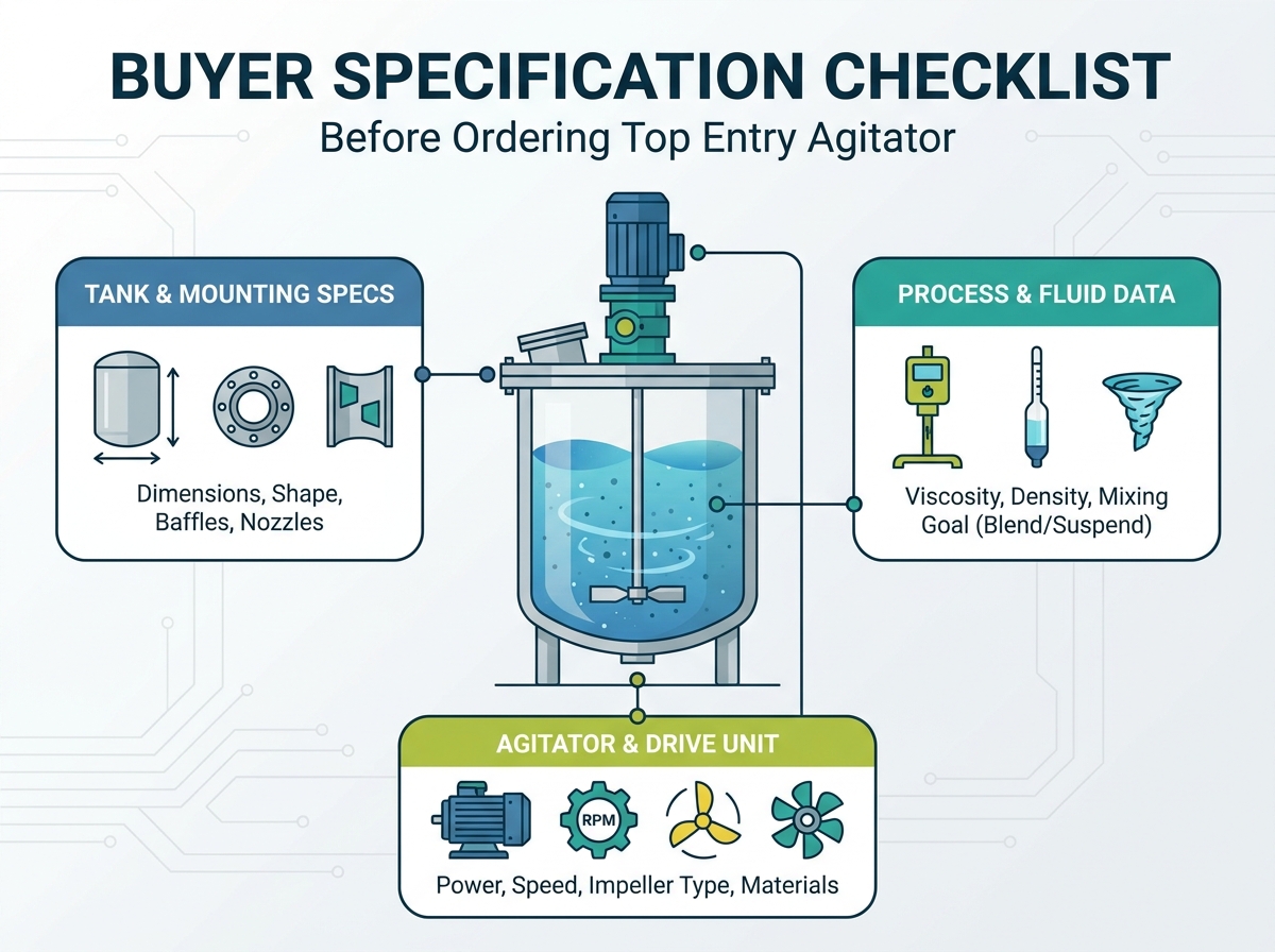
Improper mixing equipment selection carries high stakes for any processing facility. Undersized units lead to poor product yield and inconsistent batches. Oversized units inflate capital expenditure and drive up energy consumption unnecessarily. The core problem often lies in a communication gap between process engineers and equipment manufacturers. Vague requests for quotes result in inaccurate proposals. This ultimately leads to mechanical failures like bent shafts and blown seals, or severe process inefficiencies. A rigorous specification framework is necessary to prevent these issues. This guide serves as a comprehensive checklist to define process, mechanical, and operational requirements before ordering a top entry tank agitator.
Accurate fluid rheology (viscosity and specific gravity under operating conditions) is the foundational metric for sizing motors and gearboxes.
Tank geometry—specifically the aspect ratio and baffle configuration—dictates whether a top entry configuration is viable or if side entry is required.
Mechanical integrity relies on calculating shaft critical speed and bending moments to prevent catastrophic failure during operation.
Evaluating quotes based solely on upfront price ignores long-term operational expenses, which are heavily influenced by energy consumption and maintenance downtime.
Understanding structural and process differences is the first step in mixer selection. Top-entry models account for approximately 90% of industrial applications due to their versatility across diverse viscosity and gravity levels. These units are vertically mounted and uniquely engineered to achieve full-depth agitation across the entire liquid column. You mount them on the top head or bridge of the vessel, allowing the shaft to extend downward into the fluid.
Side entry mixers present distinct limitations. They require high maintenance on submerged seals and are generally limited to low-viscosity or horizontal flow applications. If a mechanical seal fails on a side-entry unit, you often have to drain the entire tank to replace it, causing massive downtime. However, tank geometry dictates feasibility. When a tank's diameter is significantly wider than its height—specifically when the aspect ratio exceeds 1:1.75 (width-to-fluid-level)—side-entry mixers become more practical. Standard vertical aspect ratios heavily favor top-entry units.
Feature | Top Entry Agitator | Side Entry Agitator |
|---|---|---|
Mounting Location | Tank roof or structural bridge | Lower sidewall of the tank |
Seal Maintenance | Accessible, above fluid level | Submerged, requires tank draining |
Viscosity Handling | Low to extremely high (100,000+ cPs) | Low viscosity only (typically < 500 cPs) |
Ideal Tank Geometry | Tall, vertical cylinders (1:1 to 1:1.5 ratio) | Wide, flat tanks (ratio > 1:1.75) |
Selecting the right mechanical configuration ensures operational efficiency. The four most common overhead designs serve specific process needs. You must match the drive type to the fluid's resistance and the required flow pattern.
Direct-Drive Top Entry: High-speed, low-torque units ideal for low-viscosity water-like fluids and rapid dispersion tasks. These run at motor speed, typically 1750 or 1150 RPM.
Gear-Driven Top Entry: Low-speed, high-torque units designed for high-viscosity media and large-scale blending operations. The gearbox reduces speed to anywhere from 20 to 350 RPM, multiplying the torque to turn massive impellers.
Portable/Clamp-On Top Entry: Flexible, entry-level mounting designs suitable for open-top tanks and rapid operational changes. You see these often in 55-gallon drum mixing or small tote blending.
Heavy-Duty Custom Overhead Designs: Rigidly mounted, custom-engineered structural bridge designs built to withstand extreme dynamic forces in high-volume industrial processing. These feature oversized bearings and heavy-duty pedestals.
The physical dimensions of the vessel heavily influence agitation dynamics. An ideal aspect ratio of 1:1 to 1:1.5 (height to diameter) is optimal for standard overhead mixing. Extreme aspect ratios, such as tall and narrow tanks, require multiple impeller tiers or steady bearings to maintain full-depth agitation and prevent shaft deflection. If you have a tank that is 30 feet tall but only 10 feet wide, a single impeller at the bottom will not mix the top 15 feet of fluid effectively.
Varying fluid levels also present challenges. Tanks that require continuous agitation during filling or draining must be specified carefully. When impellers break the liquid surface, they experience uneven loading. This causes splashing, vortexing, and excessive shaft vibration. Engineers solve this by specifying variable frequency drives (VFDs) to slow the mixer down as the fluid level drops, or by designing the shaft to withstand the severe bending moments of surface-breaking operation.
Fluid resistance defines power requirements. Process engineers must distinguish between dynamic viscosity and kinematic viscosity when submitting specifications. Dynamic viscosity measures internal resistance to flow, while kinematic viscosity divides dynamic viscosity by fluid density. You must provide these values at the actual operating temperature, as viscosity drops significantly when fluids are heated.
Non-Newtonian fluids complicate this further. Shear-thinning (thixotropic) or shear-thickening (dilatant) behaviors fundamentally alter impeller selection and torque requirements. A fluid that thickens under agitation demands a robust gear-driven system to prevent motor stalling. Conversely, shear-thinning fluids like ketchup or paint require impellers that can maintain flow even as the apparent viscosity drops near the blades but remains thick at the tank walls.
Fluid Type | Behavior Under Agitation | Engineering Requirement |
|---|---|---|
Newtonian (Water, Oil) | Viscosity remains constant | Standard power calculations apply |
Shear-Thinning (Paint, Sludge) | Viscosity decreases | Requires large diameter impellers for wall-to-wall flow |
Shear-Thickening (Cornstarch slurry) | Viscosity increases | Requires high-torque gearboxes and heavy-duty shafts |
Specific gravity directly impacts the horsepower required to move the fluid. Calculating power requirements based on water (specific gravity of 1.0) is a massive error when the actual product is significantly denser. Heavier fluids require larger motors and stronger shafts to handle the increased load without compromising rotational speed.
For example, a 25% limestone slurry might have a specific gravity of 1.3. This means it requires 30% more horsepower to mix than water. If you size the motor for water, the agitator will trip the motor overloads immediately upon startup. Always specify the maximum possible specific gravity your process might encounter, including worst-case scenarios like cold startups or higher-concentration batches.
Applications involving solids require precise flow calculations. Failing to account for settling velocity results in solid accumulation at the tank bottom, ruining batch consistency and potentially burying the impeller in a solid mass. When specifying a mixer for solids, you must define the exact level of suspension required.
On-Bottom Motion: Solids are moving along the tank floor but are not lifted into the fluid column. This requires the least power.
Off-Bottom Suspension: All particles are lifted off the tank floor, but the concentration is higher at the bottom than the top. This is the standard requirement for most slurry tanks.
Uniform Suspension: Solids are evenly distributed throughout the entire liquid column. This requires massive pumping capacity and high horsepower.
Particle size, density, and settling velocity dictate the required fluid velocity and impeller pumping capacity. Heavy, large particles like sand require aggressive axial flow impellers pitched to drive fluid straight down to sweep the tank floor.
Defining success criteria is mandatory for blending applications. Specifications must outline the target homogeneity, such as achieving 95% uniformity within a specific cycle time. This dictates the turnover rate and the type of axial flow impeller required to move the entire tank volume efficiently.
If you need to blend two miscible liquids like water and alcohol, a simple hydrofoil impeller will achieve homogeneity quickly with minimal power. However, blending immiscible liquids, like oil and water to create an emulsion, requires high shear. You must specify the droplet size required for the emulsion, which dictates the tip speed of the impeller and the motor horsepower.
Introducing gases into liquids for processes like fermentation, hydrogenation, or wastewater aeration requires specialized equipment. Radial impellers, such as Rushton turbines, are necessary to shear gas bubbles effectively. Proper specification prevents impeller flooding, a condition where gas overwhelms the blades and drastically reduces mixing efficiency.
When a sparge ring introduces gas below the impeller, the blades must chop the large gas bubbles into micro-bubbles to increase the surface area for mass transfer. If the gas flow rate is too high relative to the impeller speed, the gas forms a cavity behind the blades. The impeller loses its grip on the fluid, power draw drops, and mixing ceases. You must provide the exact gas flow rate (in standard cubic feet per minute) to the manufacturer to prevent this.
Agitation significantly improves heat transfer coefficients for tanks equipped with cooling jackets or internal coils. The mixer must generate sufficient fluid velocity across the heat transfer surfaces to prevent localized hot or cold spots, ensuring uniform temperature distribution throughout the batch.
In a jacketed reactor, the fluid near the tank wall heats or cools first. If the agitator does not push fluid from the center of the tank to the walls rapidly, the product at the wall can burn or freeze. Engineers specify high-flow axial impellers to maximize the velocity of the fluid sweeping past the jacket, optimizing the heat transfer coefficient and reducing batch cycle times.
Certain applications involve delicate polymers, biological cells, or flocculants. High shear forces can easily destroy these products. Specifying low-shear, high-flow hydrofoil impellers is critical for these scenarios. These impellers provide the necessary fluid movement without degrading the sensitive molecular structures of the batch.
In water treatment, flocculation requires gentle mixing to allow small particles to agglomerate into larger flocs. If the agitator runs too fast or uses a high-shear blade, it will tear the flocs apart. You must specify a maximum allowable tip speed or shear rate to ensure the manufacturer selects a large-diameter impeller running at a very low RPM.
Impellers are categorized by their primary flow pattern. Axial flow impellers, including hydrofoils and pitched blade turbines, excel at blending and solid suspension. Radial flow impellers are deployed for dispersion and high-shear applications. Impeller diameter must be specified relative to the tank diameter, typically falling within a 0.25 to 0.5 D/T (diameter-to-tank) ratio for optimal performance.
Impeller Type | Flow Pattern | Primary Application | Shear Level |
|---|---|---|---|
Hydrofoil | Axial (Downward) | Low-viscosity blending, heat transfer | Very Low |
Pitched Blade Turbine | Axial / Radial mix | Solid suspension, medium viscosity | Medium |
Rushton Turbine | Radial (Outward) | Gas dispersion, mass transfer | High |
Cowles Sawtooth | Radial | Powder wet-out, emulsification | Extremely High |
Shaft length and diameter are bound by strict engineering realities. Critical speed is the theoretical angular velocity that excites the natural frequency of the rotating shaft. The agitator's operating speed must remain safely below the first lateral critical speed—typically under 85%—to avoid destructive harmonic vibrations that can shatter seals and bend the shaft.
When a shaft operates too close to its critical speed, it begins to whip. This whipping action destroys gearbox bearings and mechanical seals in a matter of hours. To increase the critical speed, engineers must either shorten the shaft or increase its diameter. Increasing the diameter adds weight and cost, but it is a non-negotiable requirement for mechanical reliability in deep tanks.
Unbaffled top-centered agitators create inefficient solid-body rotation, leading to severe swirling and vortexing. The entire fluid mass simply spins with the impeller, resulting in zero actual mixing. Standard baffle configurations usually involve four baffles spaced at 90 degrees, sized at 1/10th to 1/12th of the tank diameter.
Baffles convert the rotational energy of the fluid into vertical flow, forcing the liquid to turn over from top to bottom. In specific scenarios, such as small tanks or highly viscous fluids, off-center mounting can be utilized to eliminate the need for baffles while still disrupting the vortex. You angle the mixer 10 to 15 degrees off the vertical axis to create an asymmetrical flow pattern.
Mounting requirements vary based on vessel design. Open tanks often utilize bridge mounts, while closed pressure vessels require ANSI flanges or sanitary ferrules. Reinforcing the tank roof is an absolute necessity. The structure must handle the dynamic torque and severe bending moments generated by a heavy-duty top entry tank agitator during continuous operation.
If the tank roof is too thin, the agitator will flex the metal during operation. This flexing throws the shaft out of alignment, causing premature bearing failure and seal leakage. Always consult with the tank fabricator to ensure the nozzle or mounting bridge includes heavy gussets and thick mounting pads to absorb the dynamic loads.
Sealing options are dictated by operating pressure and environmental hazards. Lip seals and packing glands offer basic protection for low-pressure applications. Single mechanical seals provide robust containment, while double mechanical seals with barrier fluids are mandatory for highly toxic, flammable, or high-pressure environments.
V-Ring / Lip Seals: Used for dust and vapor retention in atmospheric tanks. Very low cost, but cannot handle pressure.
Packing Glands (Stuffing Boxes): Traditional sealing method using braided packing. Requires regular tightening and allows a slight weepage of gas or fluid.
Single Dry-Running Mechanical Seals: Excellent for moderate pressure vessels. They prevent fugitive emissions without needing a liquid lubrication system.
Double Mechanical Seals: The highest level of protection. A pressurized barrier fluid sits between two seal faces, ensuring zero leakage of the process fluid into the atmosphere.
Food, beverage, and pharmaceutical applications require strict adherence to sanitary standards. Specifications must include Clean-in-Place (CIP) or Sterilize-in-Place (SIP) compatibility. Equipment must meet 3-A sanitary standards, utilize FDA-compliant elastomers, and feature specific surface finishes, such as precise Ra values and electropolishing, to prevent bacterial growth.
In sanitary design, there can be no dead legs, threads, or crevices where product can accumulate. Impellers must be welded directly to the shaft and polished smooth, or attached using specialized sanitary hardware with O-ring seals. The mechanical seal must also be designed to allow CIP fluids to flush the seal faces completely during the cleaning cycle.
Buyers must avoid "apples-to-oranges" comparisons. Different manufacturers may propose vastly different impeller diameters, shaft thicknesses, or motor horsepowers for the exact same process parameters. Some vendors quote bare-minimum standard designs that fail prematurely under high-viscosity dynamic loads. Others build in conservative safety factors for long-term mechanical reliability. Standardizing RFQ responses ensures all bids are evaluated on equivalent operational baselines.
When you receive three quotes, look immediately at the proposed impeller diameter and the shaft diameter. If Vendor A proposes a 2-inch shaft and Vendor B proposes a 3-inch shaft, Vendor B is designing for a much higher bending moment and critical speed safety factor. Vendor A's unit will be cheaper upfront but carries a massive risk of mechanical failure.
Initial equipment investments are driven by material selection and mechanical complexity. Choosing between 316L Stainless Steel and exotic alloys like Hastelloy drastically alters the baseline. Motor sizing and gearbox complexity also play major roles. Buyers must weigh the benefits of sourcing standard modular systems against investing in custom-engineered overhead mixing solutions designed direct-from-manufacturer.
Exotic alloys are notoriously difficult to machine and weld. If your process requires Hastelloy C-276 for corrosion resistance, expect the shaft and impeller costs to quadruple compared to standard stainless steel. To mitigate this, some engineers specify carbon steel shafts with a fluoropolymer (PTFE) coating, which provides excellent chemical resistance at a fraction of the cost of solid exotic metals.
A cheaper, less efficient impeller design typically requires a much larger motor to achieve the same mixing result. This inefficiency results in massive amounts of wasted electricity annually. Prioritizing high-efficiency hydrofoil designs reduces continuous power draw and lowers long-term operational burdens.
Consider a continuous process running 24/7. A poorly designed pitched blade turbine might require a 50 HP motor to keep solids suspended. A highly engineered, custom-profiled hydrofoil might achieve the exact same suspension with a 30 HP motor. The energy savings from that 20 HP difference will pay for the more expensive hydrofoil impeller in less than a year.
Downtime halts production entirely. Specifying standard, readily available motors and gearboxes, such as NEMA or IEC frames, is crucial. Proprietary components extend lead times during critical failures. Reliable vendor support and accessible replacement parts ensure the facility remains operational year-round.
Always ask the manufacturer about the gearbox internals. Are the bearings and gears standard off-the-shelf components you can buy from a local power transmission supplier, or are they custom-machined parts that require a 12-week lead time from the factory? Specifying commercial off-the-shelf (COTS) wear parts is a mandatory strategy for plant maintenance teams.
Specifying industrial mixing equipment is a rigorous balancing act between process chemistry and mechanical engineering. Be highly skeptical of vendors who provide quotes without demanding detailed fluid rheology, precise tank dimensions, and explicit process objectives. To move forward effectively, follow these exact steps:
Compile your tank drawings, noting exact dimensions, baffle placements, and nozzle sizes.
Gather safety data sheets (SDS) and rheology reports for all process fluids at operating temperatures.
Define your desired cycle times, suspension levels, and homogeneity targets clearly in a written document.
Consult directly with an application engineer to initiate a formal, data-driven request for quote based on your compiled parameters.
A: Top entry agitators can handle volumes ranging from small 10-gallon pilot tanks to massive vessels exceeding 100,000 gallons, provided the structural mounting and shaft design are engineered to support the required torque and bending moments.
A: Direct drive units are best for low-viscosity fluids requiring high-speed dispersion. Gear-driven units are necessary for high-viscosity fluids or large volumes that require low-speed, high-torque blending to move the mass efficiently.
A: Baffles disrupt the circular flow of the fluid, preventing solid-body rotation and deep vortexing. This converts the rotational energy into axial or radial flow, which is required for actual top-to-bottom mixing.
A: The ideal aspect ratio (fluid height to tank diameter) is between 1:1 and 1:1.5. Tanks taller than this often require multiple impellers on the shaft to ensure full-depth agitation.
A: Higher viscosity increases the fluid's resistance to flow. This requires greater torque to turn the impeller, necessitating a larger motor and a heavy-duty gearbox to prevent stalling and mechanical failure.
A: Yes, mounting the agitator off-center and slightly angled can disrupt the flow pattern enough to prevent vortexing in unbaffled tanks, though this is typically limited to smaller volumes and specific fluid types.
A: Side-entry mixers are generally recommended when the tank diameter is significantly wider than the fluid height, specifically when the aspect ratio exceeds 1:1.75, making top-entry shafts impractically long or inefficient.