- All
- Product Name
- Product Keyword
- Product Model
- Product Summary
- Product Description
- Multi Field Search
Please Choose Your Language
Views: 0 Author: Site Editor Publish Time: 2026-07-16 Origin: Site
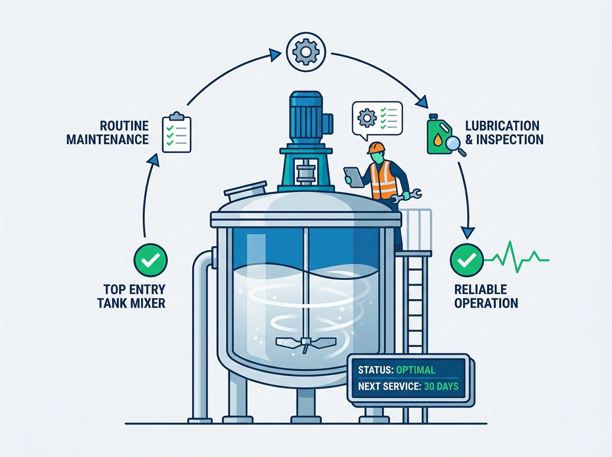
Unplanned downtime in continuous process manufacturing carries heavy financial and operational penalties. When a mixing unit fails catastrophically, the resulting production halt impacts output yields and delays downstream processing. Plant operators face intense pressure to keep systems running without interruption. Continuous duty cycles systematically degrade mechanical integrity over time. High torque demands, variable fluid viscosities, and abrasive slurries place immense dynamic stress on drive assemblies and wetted parts. Equipment operating under these harsh conditions requires more than reactive troubleshooting. Without a rigorous strategy, mechanical wear accelerates, leading to severe shaft deflection, seal breaches, and motor burnout. Implementing a structured, engineering-led maintenance framework for a top entry tank mixer serves as the primary mechanism to ensure predictable performance. Proactive component evaluation and continuous condition monitoring safeguard product quality and optimize overall operational efficiency.
Vibration and Alignment: Proactive shaft alignment and continuous vibration analysis are critical to preventing premature gearbox and mechanical seal failures.
Seal Integrity: Rigorous maintenance of mechanical seals and lubrication systems acts as the primary defense against batch contamination and catastrophic bearing wear.
Serviceability: Prioritizing in-situ maintenance capabilities, such as utilizing shaft shut-off devices to service components without draining the tank, drastically reduces operational downtime.
Predictive Shift: Transitioning from calendar-based preventative checklists to condition-based predictive maintenance maximizes equipment lifespan in high-duty applications.
Reliable continuous operation requires maintaining optimal fluid dynamics throughout the entire production cycle. The primary objective involves avoiding solids stratification and maintaining uniform suspension without inducing mechanical degradation. Equipment must deliver consistent shear and flow patterns regardless of the operational duration. Achieving this consistency demands a mechanical infrastructure capable of withstanding sustained dynamic forces without yielding. Operators monitor motor amp draw and shaft deflection to verify the system operates within designed parameters. When fluid dynamics shift due to mechanical wear, the entire batch process suffers from inconsistent blending and poor heat transfer.
Engineers define success by measuring Mean Time Between Failures (MTBF) and overall equipment effectiveness. A well-maintained unit runs for years without requiring major overhauls. You achieve this by tracking baseline performance metrics during commissioning and comparing them against daily operational data. Any deviation from the baseline indicates developing mechanical issues. Maintenance teams use this data to schedule interventions before minor wear escalates into catastrophic failure.
Fluctuating viscosities during batch processing place dynamic, asymmetrical loads directly on the mixer shaft and drive assembly. As fluid resistance increases, the motor and gearbox must instantly compensate to maintain impeller speed. These sudden torque spikes generate intense mechanical stress across the entire drive train. Over time, these variable loads fatigue metal components, leading to micro-fractures in shafts and accelerated wear on gear teeth. The drive system absorbs these shocks, but the internal bearings and gear meshes take the brunt of the impact.
Operators frequently encounter non-Newtonian fluids that thicken under shear stress. This thickening effect forces the motor to draw more current, pushing the electrical and mechanical systems to their thermal limits. Gearbox output shafts experience severe torsional strain during these high-viscosity phases. You must select lubricants that maintain film thickness under these extreme pressure conditions. Failure to manage these torque spikes results in sheared coupling bolts, twisted shafts, and shattered gear teeth.
Processing high-solid or abrasive media significantly accelerates erosion rates on wetted parts, particularly impellers and lower shafts. Particulate matter acts as a continuous grinding agent against metal surfaces. This erosion alters the precise geometry of the impeller blades, which directly reduces mixing efficiency and flow generation. As blades lose their optimal shape, the system requires more power to achieve the same mixing results, further straining the motor. The leading edges of the blades suffer the most severe material loss.
Slurry Type | Abrasive Characteristic | Expected Wear Rate | Recommended Impeller Material |
|---|---|---|---|
Limestone Slurry | Moderate to High | 0.5mm - 1.0mm / year | Rubber-lined Carbon Steel |
Titanium Dioxide | High | 1.0mm - 2.5mm / year | Hardened Stainless Steel (e.g., 440C) |
Silica Sand Suspension | Extreme | 2.0mm - 4.0mm / year | Ceramic Coated or High-Chrome Alloy |
Biological Sludge | Low | < 0.2mm / year | Standard 316L Stainless Steel |
Maintenance personnel must track the reduction in blade diameter and thickness over time. When an impeller loses more than 10% of its original diameter, flow characteristics change drastically. The pump-down effect weakens, allowing solids to settle at the bottom of the vessel. You must schedule impeller replacements or apply hard-facing weld overlays before the erosion compromises the structural integrity of the hub connection.
Thermal imaging and acoustic sensors provide critical data for detecting overheating or abnormal gear meshing before a catastrophic failure occurs. Routine acoustic monitoring identifies subtle changes in bearing frequencies. Establishing strict intervals for gearbox oil sampling, analysis, and replacement remains non-negotiable. Oil degradation directly increases gear tooth wear and elevates operating temperatures. Maintenance teams must also ensure breather vents remain clear to prevent internal pressure buildup. Procedures for verifying drive belt tension, inspecting for fraying, and checking coupling tolerances ensure highly efficient power transmission.
Gearbox maintenance requires a systematic approach to lubrication management. You cannot rely solely on visual oil level checks. Oil analysis reveals microscopic metal wear particles, water contamination, and changes in viscosity. When the analysis shows elevated iron or bronze levels, mechanics know internal wear is accelerating. They can then schedule a controlled shutdown to inspect the gear teeth and bearings. Replacing a worn bearing costs a fraction of replacing a completely destroyed gearbox.
Minor deviations in shaft alignment amplify stress exponentially on the gearbox bearings and mechanical seals. Even a fraction of a millimeter of misalignment introduces severe radial loads. Technicians must use dial indicators and laser alignment tools to measure shaft runout accurately. These measurements ensure the shaft remains strictly within OEM specifications. Worn bearings or bent shafts can shift the equipment's natural frequency. This shift frequently leads to destructive harmonic vibration, which can shatter mechanical seals and fracture mounting structures.
Executing a proper shaft alignment requires specific, sequential steps to guarantee accuracy and prevent induced stress on the drive components.
Isolate the motor electrically and apply lockout/tagout (LOTO) devices to ensure absolute safety during the procedure.
Clean the mounting flanges, coupling faces, and shaft surfaces thoroughly to remove any rust, dirt, or old grease that could skew measurements.
Mount the laser alignment brackets securely to the motor shaft and the gearbox input shaft, ensuring they are rigid and will not slip during rotation.
Rotate the shafts simultaneously to 9, 12, and 3 o'clock positions, recording the laser readings at each point to map the angular and parallel misalignment.
Calculate the required shim adjustments for the motor feet based on the laser system's output.
Insert precision pre-cut stainless steel shims under the motor feet to correct the vertical alignment.
Adjust the motor horizontally using the jacking bolts until the laser indicates the alignment falls within the specified tolerance (typically less than 0.002 inches).
Tighten the motor hold-down bolts to the specified torque and perform a final sweep with the laser to verify the alignment did not shift during tightening.
Routine visual and non-destructive testing (NDT) inspections are vital for evaluating axial flow and radial flow impellers. Inspectors must look for cavitation damage, leading-edge erosion, and fatigue cracking near the hub. Impeller wear correlates directly to a measurable drop in mixing efficiency. For example, worn axial flow impellers fail to maintain solids in suspension, resulting in material accumulation at the tank bottom and extended batch times. Checking hub set screws and bolted blade connections is essential, as these fasteners frequently loosen under continuous operational vibration.
Mechanics use dye penetrant testing to find microscopic cracks in the impeller welds. These cracks propagate rapidly under the cyclic loading of continuous mixing. If a blade snaps off during operation, the resulting severe imbalance will instantly destroy the gearbox bearings and bend the main shaft. You must replace or repair cracked impellers immediately. Never attempt to run a mixer with a known structural defect in the wetted parts.
Barrier fluid systems for double mechanical seals require precise maintenance, including daily pressure monitoring and routine fluid top-offs. Loss of barrier pressure immediately compromises the seal faces. Bearing and seal lubrication protocols demand strict adherence to volume and frequency guidelines. Under-greasing causes severe friction and premature wear, while over-greasing blows out seals and introduces contaminants. Maintenance personnel must establish strict protocols for identifying early signs of seal face wear or elastomer degradation. Early detection prevents product leakage and atmospheric contamination.
The mechanical seal acts as the primary barrier between the process fluid and the outside environment. When handling hazardous or flammable chemicals, seal integrity becomes a critical safety issue. Operators monitor the barrier fluid reservoir for pressure drops or fluid discoloration. If the barrier fluid turns cloudy or matches the color of the process media, the inboard seal face has failed. Mechanics must pull the seal cartridge and rebuild it before the outboard face also fails, which would release chemicals into the plant.
Process media hardening or accumulating on the shaft and impeller blades introduces severe mechanical imbalance. This material buildup causes dynamic runout, increases vibration, and creates localized contamination zones. Implementing rigorous cleaning procedures preserves the structural and hygienic integrity of all wetted components. Maintenance teams should utilize safe mechanical cleaning methods combined with Clean-in-Place (CIP) cycle verification. Proper decontamination prevents abrasive buildup from damaging seals during startup sequences.
CIP systems rely on high-pressure spray balls to remove residue from the mixer shaft and blades. However, shadow areas behind the impeller hubs often require manual intervention. Operators must inspect these areas visually after the CIP cycle completes. If residue remains, they must use long-handled brushes or high-pressure lances to remove the hardened material. Leaving residue on the blades guarantees an out-of-balance condition when the mixer restarts.
Effective maintenance starts with disciplined daily and weekly routines. Operators must perform visual inspections for leaks, listen for abnormal noise, verify barrier fluid levels, and monitor housing temperatures. Monthly and quarterly routines require more invasive checks. These include grease application, belt tensioning, fastener torque verification, and capturing basic vibration readings. Annual turnarounds involve comprehensive internal gearbox inspections and complete oil changes. During this time, teams execute thorough cleaning of internal and external assemblies and perform complete shaft runout evaluations.
Task Frequency | Maintenance Action | Target Component | Acceptable Tolerance / Condition |
|---|---|---|---|
Daily | Check barrier fluid pressure | Double Mechanical Seal | 15-20 PSI above vessel pressure |
Weekly | Monitor motor housing temperature | Electric Motor | Below 85°C (185°F) |
Monthly | Grease motor bearings | Motor Bearings | 2-3 pumps of polyurea grease |
Quarterly | Measure overall vibration velocity | Gearbox Housing | Less than 4.5 mm/s RMS |
Semi-Annually | Sample and analyze gearbox oil | Gearbox Lubricant | Zero water, normal viscosity, low wear metals |
Annually | Check shaft runout with dial indicator | Main Mixer Shaft | Maximum 0.005 inches per foot of shaft length |
Transitioning to condition-based monitoring significantly improves equipment reliability. Installing permanent vibration sensors and IoT-enabled motor monitors allows teams to track equipment health in real-time. Analyzing historical wear data empowers maintenance teams to replace components precisely before the point of failure. This data-driven approach eliminates the reliance on arbitrary calendar dates for parts replacement. Predictive technologies maximize the lifespan of critical components while drastically reducing the risk of unexpected breakdowns.
Vibration analysts look for specific fault frequencies in the spectral data. An inner race bearing defect generates a distinct frequency peak that grows in amplitude as the wear worsens. By trending this data over months, the analyst can predict exactly when the bearing will fail. The maintenance planner then orders the replacement parts and schedules the repair during a planned production outage. This eliminates the chaos and lost revenue associated with emergency breakdowns.
Evaluating equipment design prior to installation yields significant long-term benefits. Designs incorporating mechanical shaft shut-off devices, such as metal-to-metal seating collars, seal the tank internally. These shut-off devices allow maintenance teams to replace mechanical seals or bearings safely without requiring tank drainage. This eliminates the need for product transfer or hazardous confined space entry. While highly serviceable mixer designs carry a higher upfront capital cost, they provide massive long-term savings through drastically reduced downtime and labor requirements.
When a seal fails on a standard mixer, operators must empty the entire vessel, clean it, and issue confined space permits before mechanics can build scaffolding to support the shaft. This process takes days. With a shaft shut-off device, mechanics engage the collar, lock the shaft in place, and remove the seal cartridge from the top of the unit. The entire replacement takes a few hours, and the process fluid remains safely inside the tank.
Categorizing inventory correctly prevents extended maintenance delays. High-turnover consumables, including o-rings, specific lubricants, and lip seals, must always remain in stock. Critical insurance spares, such as mechanical seal cartridges, primary bearings, and spare impeller blades, protect against catastrophic delays. Long lead times for custom-machined parts present a severe risk to continuous operations. Facilities must keep specific shafts and custom impellers in local stock to mitigate supply chain disruptions effectively.
Plant managers must audit their storerooms regularly to ensure spare parts remain in usable condition. Elastomers degrade over time, even sitting on a shelf. Mechanics should rotate the shafts of spare gearboxes every month to prevent false brinelling of the bearings and to keep the internal components coated in oil. Storing a spare mechanical seal in a climate-controlled environment prevents the carbon faces from warping and the o-rings from drying out.
Reliable continuous operation results directly from rigorous, data-driven maintenance execution rather than initial equipment quality alone. Engineering and procurement teams must evaluate new mixer purchases based heavily on serviceability features and predictive monitoring compatibility. Prioritizing in-situ seal replacement capabilities ensures rapid recovery from mechanical wear.
Audit your current mixer maintenance checklists to ensure alignment with OEM specifications.
Consult with an applications engineer to perform a comprehensive reliability assessment on your existing units.
Integrate continuous vibration monitoring sensors on all critical continuous-duty mixing equipment.
Upgrade mechanical seal support systems to include automated pressure and fluid level alerts.
A: Gearbox oil changes typically occur every 2,500 to 4,000 operating hours, depending on the manufacturer's specifications and operational load. Continuous high-torque applications require more frequent changes. Always perform regular oil sampling to detect metal shavings or thermal degradation before scheduling the replacement.
A: Excessive vibration usually stems from shaft misalignment, severe bearing wear, or mechanical imbalance caused by material buildup on the impeller blades. Operating the mixer at or near its critical speed also induces destructive harmonic vibrations that require immediate operational adjustment.
A: Yes, if the mixer design includes a mechanical shaft shut-off device. This mechanism uses a seating collar to seal the tank internally, allowing technicians to safely remove and replace the mechanical seal cartridge without draining the process fluid or entering the vessel.
A: Technicians use precision dial indicators and laser alignment tools to measure runout. The indicator is mounted to a fixed point while the shaft is manually rotated. Measurements are taken at multiple points along the shaft to ensure deviations remain strictly within the required OEM tolerances.
A: Regular visual and non-destructive testing (NDT) inspections are critical. Operators should monitor the leading edges for erosion and check the hub for fatigue cracking. Applying specialized hardened coatings or utilizing abrasion-resistant alloys during the initial purchase significantly extends the impeller's operational lifespan.
A: Viscosity fluctuations create variable, asymmetrical loads that cause sudden torque spikes. This dynamic stress accelerates wear on gear teeth, bearings, and drive belts. Mixers handling highly variable viscosities require more frequent vibration analysis and tighter lubrication intervals to prevent premature mechanical failure.