- All
- Product Name
- Product Keyword
- Product Model
- Product Summary
- Product Description
- Multi Field Search
Please Choose Your Language
Views: 0 Author: Site Editor Publish Time: 2026-07-25 Origin: Site
Achieving fluid homogeneity in tall, narrow industrial tanks presents a distinct engineering challenge. When agitation energy fails to penetrate the full liquid column, operators face severe process bottlenecks. Dead zones form at the tank bottom, product quality degrades due to inconsistent blending, batch times stretch beyond acceptable limits, and agitator shafts endure excessive mechanical strain from unbalanced fluid forces. Solving these problems requires a precise approach to fluid dynamics and structural design rather than simply increasing motor horsepower.
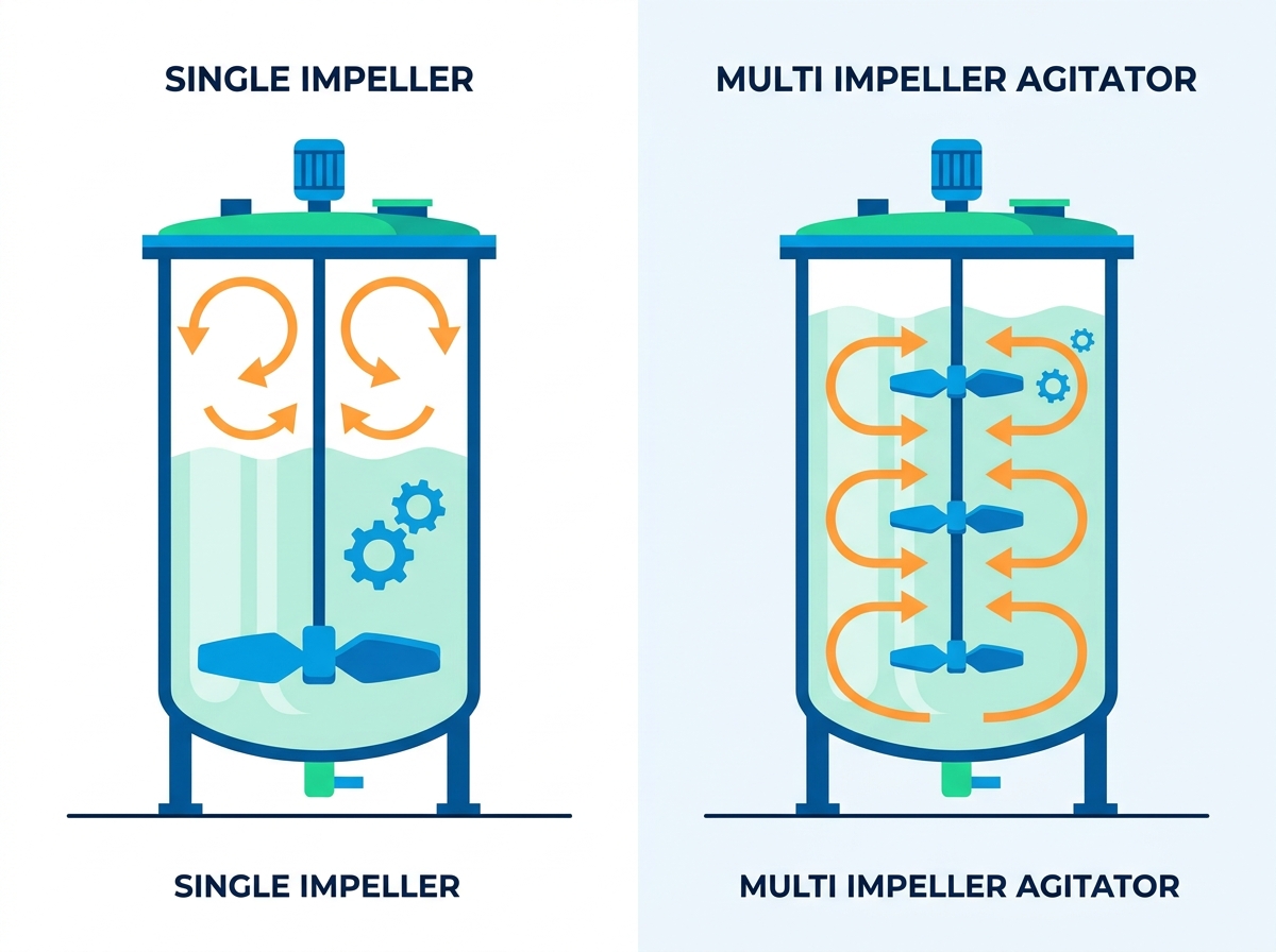
The fundamental engineering decision comes down to scaling up a single impeller versus engineering a multi impeller agitator. This choice dictates mixing efficiency, power consumption, structural integrity, and long-term maintenance requirements. Understanding the physical constraints of deep tank mixing is essential for specifying the correct equipment, preventing stratification, and ensuring reliable operations across varying fluid viscosities.
The Z/T Ratio Rule: A Liquid Height to Tank Diameter (Z/T) ratio greater than 1.2 is the standard threshold where a multi impeller agitator typically becomes necessary to prevent dead zones.
D/T Ratio Adjustments: While single impellers often use larger Impeller-to-Tank (D/T) ratios, multi-impeller configurations typically utilize smaller D/T ratios (0.3 to 0.4) to manage cumulative motor load and limit shaft deflection.
Flow Pattern Complexity: Multiple impellers do not simply multiply mixing power; they create compartmentalized flow zones that must be carefully spaced to avoid counter-productive flow interference.
The Mixing Time Paradox: Contrary to assumption, adding impellers can sometimes increase overall blend time due to zone segregation; system design must balance homogeneity requirements with cycle time.
Mechanical Trade-offs: Multi-impeller systems require longer shafts, increasing the risk of shaft deflection, altering critical speed, and demanding more robust seal and bearing designs.
Successful mixing in deep tanks depends on achieving specific, measurable process outcomes. These criteria often include uniform solids suspension, rapid thermal transfer across heating jackets, and strict blend times for chemical reactions. If the agitation system cannot distribute mechanical energy evenly throughout the vessel, the process fails to meet these requirements. You end up with off-spec products, wasted energy, and extended cycle times. In industrial fermentation or polymer production, even minor deviations in fluid homogeneity can ruin an entire batch.
The Z/T ratio compares the liquid height (Z) to the tank diameter (T). Tall, narrow tanks naturally have high Z/T ratios, fundamentally altering how fluid moves within the vessel. Standard D/T (Impeller Diameter to Tank Diameter) ratios fail to account for vertical fluid dynamics in tall tanks. They only address radial reach, ignoring the vertical energy required to move fluid from the bottom dish to the top surface.
Z/T Ratio Guidelines for Agitator Selection | |||
Z/T Ratio | Tank Geometry | Recommended Agitator Configuration | Primary Flow Challenge |
|---|---|---|---|
< 0.8 | Squat / Shallow | Single Impeller (Axial or Radial) | Surface vortexing, poor radial distribution |
0.8 - 1.2 | Standard Cylinder | Single Impeller (Large D/T) | Balancing top-to-bottom turnover |
1.2 - 2.0 | Tall / Deep | Dual Impeller System | Stratification, bottom dead zones |
> 2.0 | Column / Tower | Three or more Impellers | Severe zonal segregation, shaft deflection |
When agitation energy fails to penetrate the full liquid column, fluid mechanics at the top and bottom of deep tanks degrade rapidly. Stratification occurs as heavier components settle and lighter components rise. Dead zones form where fluid velocity drops to near zero. This prevents proper blending and allows solids to accumulate on the tank floor. In chemical reactors, these stagnant areas can cause localized overheating or uncontrolled side reactions, posing significant safety risks.
Single impellers operate best within specific geometric and rheological limits. They are highly effective when the Z/T ratio is less than 1.2 and D/T ratios range from 0.35 to 0.5. These systems excel in applications involving low-to-medium viscosity, Newtonian fluids where a single flow pattern easily encompasses the entire batch volume. Water treatment facilities and simple blending tanks rely heavily on single-stage hydrofoils for efficient, low-shear mixing.
Simply increasing a single impeller's diameter or rotational speed in a deep tank yields diminishing returns. This brute-force approach leads to runaway power consumption and localized high shear near the impeller blades, while distant fluid remains stagnant. You will observe several distinct failure modes when a single impeller is pushed beyond its geometric limits:
Severe Surface Vortexing: High speeds create deep vortices that draw unwanted air into the product, causing foaming and oxidation.
Excessive Localized Shear: Sensitive products like shear-thinning polymers or biological cultures suffer damage near the blade tips.
Bottom-Tank Settling: Heavy slurries drop out of suspension, forming a solid cake on the tank floor that requires manual removal.
Shaft Vibration: Unbalanced fluid forces push against the single impeller, causing the shaft to wobble and prematurely wearing out mechanical seals.
A multi impeller agitator distributes mechanical energy across the vertical axis. By placing multiple impellers on a single shaft, the system generates distinct flow patterns that work together to turn over the entire tank volume. This ensures kinetic energy reaches both the top surface and the bottom dish. Instead of relying on one massive surge of fluid, the system creates a controlled relay of fluid motion from one stage to the next.
Multiple impellers interact on a single shaft to create complex fluid dynamics. However, there is a significant risk of creating isolated mixing zones, known as zonal segregation. In these cases, fluid loops back on itself within a specific zone instead of blending with the rest of the tank. This severely hinders overall homogeneity. Engineers must calculate the exact spacing required to force fluid exchange between these zones, breaking down the invisible boundaries that form between impellers.
Engineers frequently combine different impeller types on a single shaft to optimize performance for specific process demands. A common configuration uses a radial flow turbine at the bottom for gas dispersion or solids suspension, paired with axial flow hydrofoils above for bulk turnover. This strategic pairing maximizes the specific strengths of each impeller type.
Common Mixed-Flow Impeller Configurations | |||
Bottom Impeller | Upper Impeller(s) | Primary Application | Process Benefit |
|---|---|---|---|
Rushton Turbine (Radial) | High-Efficiency Hydrofoils (Axial) | Aerobic Fermentation | Excellent gas dispersion at the sparger, high volume turnover above. |
Pitched Blade Turbine (Mixed) | Pitched Blade Turbines (Mixed) | High Viscosity Blending | Strong shear and axial flow to move thick, sticky fluids. |
Retreat Curve (Radial) | Marine Propellers (Axial) | Glass-Lined Reactors | Low clearance sweeping at the bottom, gentle blending above. |
While standard vertical top-entry mixers are common, specialized submersible multi-impeller systems push liquid in varied directions to prevent stratification in massive horizontal or underground containment vessels. These designs adapt the multi-impeller concept to unique geometries where vertical shafts are impractical. They are frequently deployed in municipal wastewater treatment basins or large-scale agricultural slurry tanks to maintain constant motion across wide, shallow areas.
Empirical research shows that mixing time for a multi-stage system can be significantly higher than a single-impeller setup if flow zones do not properly interact. Optimizing spacing is critical to ensure inter-stage fluid exchange and break down compartmental boundaries. If impellers are placed too far apart, the fluid between them stagnates. If they are too close, they fight each other, wasting energy and creating chaotic, inefficient turbulence. Proper spacing reduces the total blend time by ensuring a continuous vertical loop.
Power draw scales with the addition of impellers, but the cumulative draw is not always strictly linear due to fluid shielding effects. Calculating the total power number in multi-stage setups requires accounting for how the flow from one impeller affects the resistance encountered by another. When an upper impeller pushes fluid directly into a lower impeller, the lower impeller experiences a reduced apparent viscosity and lower drag. Engineers must size motors and gearboxes based on these complex interaction factors, not just simple multiplication.
Deep tanks require extended shaft lengths, increasing the risk of shaft deflection and altering the critical speed. Engineering calculations must carefully evaluate bending moments and ensure the operating speed remains safely away from the shaft's natural resonant frequency. Operating too close to critical speed causes catastrophic vibration, destroying seals, bearings, and eventually the shaft itself. Thicker shafts, steady bearings at the tank bottom, or specialized hollow pipe shafts are often required to maintain rigidity over long vertical drops.
Standard baffle guidelines must be adapted for multi-impeller systems. Typically, tanks use four baffles with a width of 1/12th the tank diameter, offset slightly from the wall to prevent dead spots behind them. In deep tanks with multiple impellers, baffle optimization strategies are necessary to prevent unmitigated swirling and convert rotational energy into axial flow. Without proper baffling, the entire fluid mass simply spins in a solid cylinder, offering zero actual mixing or shear.
Proper impeller spacing prevents flow collision and zonal isolation. The standard engineering rule of thumb dictates spacing impellers 1.0 to 1.5 times the impeller diameter apart. This ensures flow patterns complement rather than fight each other. For highly viscous fluids, this spacing might be reduced to ensure the flow from one blade directly feeds the next, preventing the fluid from stalling in the gaps.
Running a multi-stage agitator while a tank is filling or draining poses significant operational risks. When an upper impeller breaks the liquid surface, it causes severe mechanical vibration and shaft whip. The uneven fluid resistance across the blades creates massive lateral forces. Operators must manage liquid levels carefully. Utilizing Variable Frequency Drives (VFDs) allows the system to slow down or shut off specific stages as the liquid level drops, mitigating these destructive forces.
Cleaning, inspecting, and replacing multiple impellers adds complexity to maintenance routines, especially in sanitary food processing or highly corrosive chemical applications. CIP systems must be designed to ensure cleaning fluids reach all surfaces of the multi-impeller assembly. Shadow areas behind blade hubs or set screws can harbor bacteria or cross-contamination. Welded, polished assemblies are often preferred over bolted hubs in these environments to eliminate crevices.
Choosing between a single impeller and a multi-impeller agitator depends on more than tank volume or motor power. Tank geometry, especially the liquid-height-to-diameter ratio, determines whether one impeller can circulate fluid through the entire vessel or whether additional stages are needed to prevent stratification and bottom dead zones.
Multiple impellers can distribute mixing energy more evenly in tall tanks, but simply adding more blades does not guarantee faster or better mixing. Impeller type, diameter, spacing, baffling, and flow direction must be coordinated so that individual circulation zones exchange fluid rather than remain isolated.
The longer shaft and higher cumulative load also require careful checks for deflection, critical speed, seal loading, and vibration. In practice, the best configuration is the one that achieves the required homogeneity while maintaining reasonable power consumption, mechanical stability, and manageable maintenance requirements.
A: A Z/T ratio greater than 1.2 generally requires multiple impellers. Tall, narrow tank geometries prevent a single impeller from pushing fluid through the entire vertical column, necessitating additional stages to eliminate dead zones and maintain uniform suspension.
A: Single impellers often use D/T ratios up to 0.5. Multi-impeller systems usually reduce this ratio to 0.3–0.4 to prevent overloading the motor and to limit the bending moments on the longer, more vulnerable shaft.
A: No. Improper spacing creates isolated mixing zones that actually increase total blend time. Fluid must exchange vertically between these zones to achieve full tank homogeneity, which requires precise engineering of the impeller gaps.
A: The standard spacing rule is 1.0 to 1.5 times the impeller diameter apart. This distance depends heavily on fluid viscosity, tank baffling, and the specific types of impellers being utilized in the process.
A: Yes. A common mixed-flow configuration uses a lower radial impeller for gas dispersion or solids suspension and upper axial impellers for efficient bulk blending and rapid tank turnover.
A: Power draw is cumulative when adding impellers, though not always strictly linear due to flow interactions and fluid shielding. Motors and gearboxes must be carefully sized to handle the total calculated load across all stages.