- All
- Product Name
- Product Keyword
- Product Model
- Product Summary
- Product Description
- Multi Field Search
Please Choose Your Language
Views: 0 Author: Site Editor Publish Time: 2026-06-18 Origin: Site
Incorrectly sizing industrial agitators introduces severe operational and financial risks to processing facilities. A miscalculated shaft length or ignored critical speed leads to catastrophic mechanical failure, destroying equipment and causing extended downtime. Beyond hardware damage, poor sizing frequently results in ruined product batches, inconsistent yields, and excessive energy consumption. Facilities cannot afford to guess when configuring heavy-duty mixing equipment.
Specifying equipment for industrial tanks requires balancing complex fluid dynamics with strict mechanical constraints. Engineers evaluate viscosity profiles and specific gravity while simultaneously calculating shaft deflection limits and critical speeds. A perfectly designed impeller is useless if the mounting structure cannot handle the dynamic loads or if the motor lacks the torque to overcome fluid resistance during a cold start.
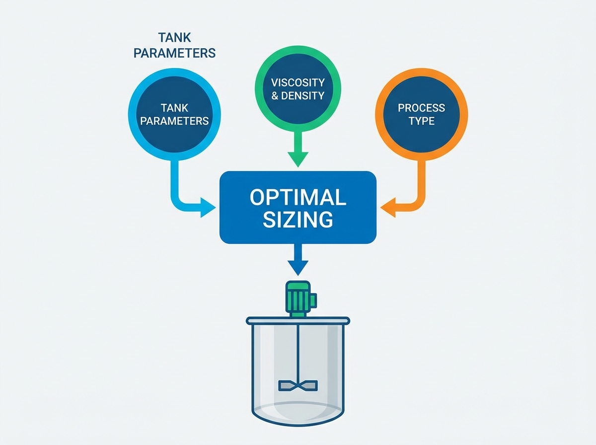
Solving these challenges demands a systematic, engineering-first framework. Properly sizing a top entry tank mixer moves sequentially from analyzing process requirements and tank geometry to selecting the right impeller, verifying mechanical design, and accommodating spatial configurations.
Fluid Properties Dictate Power: Accurate measurement of specific gravity and dynamic viscosity at operating temperatures is the non-negotiable first step in calculating motor torque and power requirements.
Geometry Influences Flow: Tank aspect ratios (ideally 1:1 for solids dissolution) and proper baffle integration are critical to prevent solid body rotation and vortexing.
Impeller-to-Tank Ratio (D/T) is Critical: Selecting the correct impeller type (axial vs. radial) and diameter relative to the tank ensures optimal pumping capacity without inducing destructive mechanical loads.
Mechanical Integrity Overrides Process Goals: Even the most efficient process design will fail if shaft critical speed, mounting structural limits, spatial headroom, and maintenance access are not rigorously calculated and mitigated.
Every mixing application begins with a defined process objective. Whether the goal is miscible liquid blending, solids suspension, gas dispersion, or heat transfer, the desired outcome dictates the required turnover rate. Blending two low-viscosity liquids requires a different flow regime than suspending heavy abrasive particles. The turnover rate, defined as the time required to pump the entire tank volume through the impeller zone, directly informs the pumping capacity needed from the agitator. You must define this target before looking at hardware.
For example, a rapid blending application might require a turnover rate of one minute, while a gentle storage agitation task might only need a turnover every ten minutes. We calculate the required pumping rate (Q) by dividing the tank volume by the desired turnover time. This baseline metric drives the rest of the sizing process.
Mechanical reliability ensures the agitator operates continuously without self-destruction. Preventing shaft deflection is paramount. Excessive bending forces wear down seals and bearings prematurely. Gear reducer wear must be minimized by selecting appropriate service factors based on the application's duty cycle. Furthermore, engineers must prevent destructive vibration caused by harmonic resonance. Operating too close to the shaft's critical speed amplifies vibrations, leading to catastrophic fatigue failure.
Field experience shows that most mixer failures originate from mechanical oversight rather than process design flaws. A shaft that deflects more than 1/8 inch at the seal face will destroy a mechanical seal within weeks. We design shafts to handle the maximum fluid forces generated during the most demanding phase of the process, which is often the initial startup when the fluid is cold and highly viscous.
There is a constant conceptual trade-off between oversizing and undersizing mixing equipment. Oversizing an agitator guarantees process results but wastes electrical power and drives up capital expenditure. Conversely, undersizing the equipment saves initial costs but leads to extended batch times, off-spec product, and potential motor burnout. Precise sizing hits the optimal operating point, maximizing process efficiency while minimizing power consumption.
Fluid viscosity fundamentally changes how an impeller interacts with the batch. Sizing approaches differ significantly between Newtonian fluids, which maintain a constant viscosity regardless of shear rate, and Non-Newtonian fluids. Shear-thinning fluids decrease in viscosity as impeller speed increases, while shear-thickening fluids become more viscous. Understanding the apparent viscosity at the specific shear rate generated by the impeller is necessary to determine the correct flow regime and prevent motor stalling.
To accurately profile viscosity, follow these steps:
Measure the fluid viscosity at the exact operating temperature, as temperature swings drastically alter flow resistance.
Identify the fluid type (Newtonian, pseudoplastic, dilatant, or thixotropic) using a rheometer.
Calculate the apparent viscosity based on the estimated shear rate of the selected impeller.
Determine the Reynolds number to classify the flow regime as turbulent, transitional, or laminar.
Specific gravity directly multiplies the power draw required by the motor. Pumping water (SG of 1.0) requires less torque than pumping a heavy slurry (SG of 1.5 or higher). This increased density not only demands a larger motor and gear reducer but also significantly influences the structural load placed on the mounting flange. Accurate density measurements ensure the mechanical components are robust enough to handle the actual operating mass.
Fluid Type | Typical Specific Gravity (SG) | Impact on Motor Power |
|---|---|---|
Water / Light Solvents | 1.0 | Baseline power requirement |
Light Oils | 0.85 - 0.95 | Slightly reduced power draw |
Heavy Slurries | 1.3 - 1.8 | Requires 30% to 80% more power |
High-Density Minerals | 2.0+ | Requires massive torque and heavy-duty gearboxes |
Operating conditions dictate the physical construction of the mixer. High temperatures, extreme pressures, and the presence of corrosive or abrasive materials require careful material selection. Standard carbon steel may suffice for basic applications, but aggressive chemicals often necessitate 316L stainless steel, exotic alloys like Hastelloy, or specialized protective coatings. Additionally, these environmental factors determine the complexity of the sealing requirements to prevent hazardous leaks or contamination.
The relationship between liquid height (Z) and tank diameter (T) heavily influences mixing efficiency. An ideal 1:1 aspect ratio is generally preferred, especially for solids dissolution, as it promotes uniform flow patterns. When dealing with tall tanks where the Z/T ratio exceeds 1.5, a single impeller cannot generate sufficient turnover for the entire volume. Mitigation strategies for tall tanks typically involve utilizing multiple impellers spaced along a single shaft to ensure active mixing zones throughout the fluid column.
When configuring multiple impellers, we space them approximately one impeller diameter apart. The bottom impeller sits close to the tank floor to sweep settled solids, while the upper impellers maintain bulk flow in the upper fluid layers. This prevents stratification and ensures homogeneous blending from top to bottom.
Standard baffling is required in most cylindrical tanks to convert the rotational velocity generated by the impeller into vertical turnover. Without baffles, the fluid simply spins in a solid body rotation, creating a deep vortex and resulting in poor mixing. The standard configuration utilizes four vertical plates spaced at 90-degree intervals around the tank wall. Proper baffle width and offset from the wall prevent dead zones and optimize the power drawn by the impeller.
Baffle width should typically be 1/10th to 1/12th of the tank diameter.
Offset baffles from the tank wall by a gap equal to 1/72nd of the tank diameter to prevent material buildup.
Extend baffles from the bottom tangent line to just above the maximum liquid level.
Top-mounting an agitator requires a robust structural foundation. Engineers must evaluate nozzle loads and baseplate rigidity to ensure the tank roof can support the dynamic forces generated during operation. In unbaffled tanks, offset or angled mounting can be used to disrupt symmetrical flow and prevent vortexing, but this alters the stress distribution on the mounting flange. Headroom and footprint clearance above the tank are also critical. When physical space is limited, right-angle gearboxes provide a lower profile compared to parallel-shaft configurations, accommodating tight overhead environments.
Impellers are categorized by the primary flow pattern they generate. Axial flow impellers, such as hydrofoils and pitched blade turbines, push fluid parallel to the shaft. They are highly efficient for general blending and solids suspension, maximizing pumping capacity per unit of power. Radial flow impellers, like Rushton turbines, drive fluid outward toward the tank wall. These are utilized for gas dispersion and high-shear applications where breaking apart droplets or bubbles is more important than bulk fluid turnover.
Impeller Type | Primary Flow Direction | Best Applications | Shear Level |
|---|---|---|---|
Hydrofoil | Axial (Down/Up) | Blending, Solids Suspension | Low |
Pitched Blade Turbine | Axial / Mixed | Viscous Blending, Heat Transfer | Medium |
Rushton Turbine | Radial (Outward) | Gas Dispersion, Emulsions | High |
Anchor / Gate | Tangential | High Viscosity, Wall Scraping | Low |
The impeller diameter (D) relative to the tank diameter (T) is a foundational sizing metric. Industry-standard D/T ratios typically range from 0.2 to 0.5. Smaller ratios are often used for high-speed, low-viscosity blending, while larger ratios are necessary for highly viscous fluids to ensure motion reaches the tank walls. Selecting the correct ratio depends on balancing the desired flow characteristics with the mechanical limitations of the shaft and motor.
For a standard top entry tank mixer handling water-like fluids, a D/T ratio of 0.25 to 0.33 provides excellent turnover without overloading the motor. As viscosity climbs above 5,000 centipoise, we increase the D/T ratio to 0.4 or higher. This larger diameter physically pushes the thick fluid, compensating for the lack of turbulent momentum.
Agitator design requires analyzing the trade-off between pumping capacity and shear rate. High-flow, low-shear applications prioritize bulk movement, utilizing impellers with a high pumping number (Nq) and a low power number (Np). Conversely, low-flow, high-shear applications require impellers that impart significant energy into a localized area, characterized by a higher Np. Understanding this relationship ensures the selected impeller aligns with the specific process objective.
Calculating the required motor horsepower relies on a specific formula incorporating the impeller's power number, the fluid density, the impeller diameter, and the rotational speed (RPM). Torque is the actual twisting force applied to the shaft and is the primary factor in sizing the gear reducer. High-viscosity applications operating at low speeds require massive torque, necessitating heavy-duty gearboxes even if the overall horsepower requirement appears modest.
Shaft design is a critical safety parameter. The shaft must be engineered to operate at least 20-30% below its first critical speed. Operating at or near critical speed induces harmonic resonance, causing severe vibrations that can bend the shaft or destroy the gearbox bearings. Variables impacting required shaft thickness include the overall unsupported length, the weight of the impellers, and the hydraulic forces exerted by the fluid during operation.
To ensure shaft stability, engineers execute the following checks:
Calculate the maximum hydraulic bending moment based on fluid density and impeller geometry.
Determine the required shaft diameter to keep deflection at the mechanical seal below 0.005 inches.
Compute the first natural frequency (critical speed) of the shaft assembly in air and in fluid.
Verify the operating speed remains safely outside the 80% to 120% window of the critical speed.
Selecting the correct seal depends on tank pressure and the nature of the fluid. Vapor seals or lip seals suffice for atmospheric tanks, while single mechanical seals are required for moderate pressures. Hazardous material containment or high-pressure applications demand double mechanical seals with barrier fluids. Incorporating maintenance-friendly designs is highly recommended. Split couplings or cartridge seals allow maintenance personnel to replace wear components without dismantling the entire heavy drive assembly, significantly reducing downtime.
Industrial mixers must adhere to strict safety and sanitary standards based on their operating environment. Equipment installed in hazardous, explosive areas must meet ATEX or IECEx ratings. Pressurized applications must comply with ASME boiler and pressure vessel codes. For food, beverage, or pharmaceutical processing, the mixer construction must follow FDA and 3-A sanitary guidelines, ensuring smooth, crevice-free surfaces that prevent bacterial growth and allow for clean-in-place (CIP) procedures.
Traditional motor-driven agitators offer unmatched reliability, predictability, and scalability. They handle complex rheologies and varying fluid levels with ease. From small benchtop pilot units to massive industrial processors, mechanical mixers provide precise control over shear rates and turnover times. This predictability makes them the standard choice for the vast majority of chemical and processing applications.
Non-mechanical alternatives, such as large compressed air bubble systems, can be evaluated for specific use cases. These systems use pulsed air to create large bubbles that lift and mix the fluid. While they eliminate moving parts within the tank, they have severe limitations. They are generally ineffective in highly viscous fluids and can damage shear-sensitive products or introduce unwanted oxidation into the batch.
Poor mounting rigidity and unbalanced impellers are the primary root causes of vibration and structural fatigue. If the tank roof flexes during operation, it amplifies shaft runout. Mitigation requires dynamic balancing of the impellers at the factory and utilizing reinforced mounting nozzles or independent support bridges to isolate dynamic loads from thin-walled tanks.
Unmixed zones at the tank bottom or surface ruin batch consistency. Stratification occurs when the impeller fails to generate sufficient axial flow to turn over the entire volume. This risk is mitigated by ensuring proper impeller clearance from the tank bottom (C/T ratio). In tall tanks, adding secondary kick-up impellers near the bottom ensures heavy solids are continuously swept back into the primary mixing zone.
Scaling a mixing process from a small lab beaker to a 10,000-gallon industrial tank is never linear. Direct linear scaling usually results in severely undersized equipment. Engineers must maintain constant torque per unit volume or constant tip speed, depending on whether the process objective relies on bulk blending or shear. Accounting for the unique fluid dynamics and extended turnover times of large-scale configurations is essential for successful scale-up.
Sizing a top entry tank mixer is not simply a matter of matching motor power to tank volume. Reliable performance depends on how fluid viscosity, specific gravity, process objectives, tank geometry, baffling, impeller design, shaft length, and operating speed interact as a complete system.
The selected impeller must generate the required flow or shear, but the shaft, gearbox, seal, mounting structure, and motor must also withstand the resulting torque and dynamic loads. Mechanical checks such as shaft deflection and critical-speed analysis are therefore just as important as achieving the desired mixing result.
Because every application has different materials, tank proportions, operating conditions, and compliance requirements, standard sizing charts provide only a starting point. Accurate process data and application-specific engineering remain the most reliable way to achieve consistent mixing, reasonable energy use, and dependable equipment life.
A: While process engineers define the fluid properties, tank dimensions, and ultimate mixing goals, the mixer manufacturer or dedicated application engineer is typically responsible for the final mechanical sizing, component selection, and warranty of the equipment.
A: A 1:1 ratio of liquid depth to tank diameter is generally optimal. This configuration promotes uniform flow patterns and is particularly effective for solids dissolution and general liquid blending.
A: Vortexing is prevented by installing standard wall baffles. In smaller unbaffled tanks, mounting the mixer off-center and at an angle can disrupt symmetrical flow and achieve a similar result.
A: Maximum length is dictated by the shaft's critical speed and diameter. Lengths exceeding 20 feet often become mechanically unstable and require steady bearings installed at the tank bottom to prevent excessive deflection.
A: As viscosity increases, the flow regime shifts from turbulent to transitional or laminar. This increased resistance requires larger diameter impellers and significantly higher motor torque to maintain the necessary fluid turnover.
A: A single impeller cannot do both efficiently. For multi-purpose tanks, engineers suggest dual-impeller configurations or utilizing variable frequency drives (VFDs) to adjust speeds for different process phases.
A: Routine maintenance includes scheduled lubrication of the gear reducer, periodic vibration analysis to detect bearing wear, and regular checks on mechanical seal interfaces to prevent leaks and catastrophic in-tank failure.