- All
- Product Name
- Product Keyword
- Product Model
- Product Summary
- Product Description
- Multi Field Search
Please Choose Your Language
Views: 0 Author: Site Editor Publish Time: 2026-07-21 Origin: Site
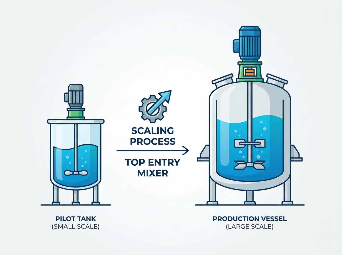
Fluid dynamics do not scale linearly. A successful formulation in a 50-gallon pilot tank is highly vulnerable to failure in a 5,000-gallon production vessel. Scale-up failures introduce massive financial and operational risks, including compromised product quality, dead zones, excessive shear stress, chemical reaction failures, and batch rejection due to mismatched mixing parameters. Translating pilot-scale success into production-scale reality requires a rigorous, mathematically grounded evaluation framework. You must understand which physical variables to hold constant and which must adapt to the new vessel geometry. Specifying the correct equipment ensures that the mechanical and fluid dynamic requirements of the production environment are met without compromising product integrity.
Scaling a top entry mixer requires prioritizing one constant (e.g., tip speed, power per unit volume, or blend time) because it is physically impossible to keep all kinematic and dynamic variables constant simultaneously.
Production-scale success depends heavily on geometric similarity; tank aspect ratios, baffle configurations, and impeller placement must be mathematically proportional to the pilot scale.
Physical configuration matters: A top entry mixer is highly preferred over side or bottom entry for hazardous, high-viscosity, or highly abrasive applications due to overhead mechanical isolation from the liquid level.
Mechanical stability becomes a primary failure point at production scale; shaft length, critical speed, and torque requirements dictate gearbox and motor specifications.
Partnering with equipment manufacturers that utilize Computational Fluid Dynamics (CFD) and scale-down modeling mitigates the risk of capital expenditure on underperforming equipment.
During scale-up, it is an engineering impossibility to maintain constant blend time, constant shear, and constant power per volume simultaneously. As vessel volume increases by the cube of the tank diameter, the surface area only increases by the square. This mathematical reality forces process engineers to choose a single primary scaling parameter based on the specific requirements of the formulation.
Choosing the correct scaling parameter dictates the entire mechanical design of the agitation system. The most common frameworks include:
Constant Tip Speed: Essential for shear-sensitive applications, emulsions, and delicate food or chemical formulations. Maintaining the same tip speed prevents the destruction of molecular structures or biological cells.
Constant Power per Unit Volume: Critical for mass transfer, gas dispersion, and fast chemical reactions. This approach ensures that the energy dissipated into the fluid remains proportional to the batch size, maintaining reaction kinetics.
Constant Blend Time: Rarely feasible at large scales due to exponential power requirements. Forcing a 5,000-gallon tank to blend as fast as a 50-gallon tank often requires massive motors that are mechanically impractical, though it remains vital for highly time-sensitive batch reactions.
Scaling Parameter | Mathematical Relationship | Primary Application | Scale-Up Limitation |
|---|---|---|---|
Constant Tip Speed | v_t ∝ N · D | Shear-sensitive emulsions, cell cultures | Blend times increase significantly at larger scales. |
Constant Power/Volume | P/V ∝ N⊃3; · D⊃2; | Gas dispersion, mass transfer, fast reactions | Tip speed increases, potentially damaging sensitive particles. |
Constant Blend Time | t_b = constant | Rapid, time-sensitive chemical reactions | Requires exponentially larger motors and extreme torque. |
Successful scale-up relies on three levels of similarity between the pilot and production vessels. Geometric similarity is the foundation. This requires maintaining proportional tank dimensions, impeller diameter-to-tank diameter ratios, and liquid height-to-diameter ratios. If the pilot tank is a perfect cylinder with a 1:1 aspect ratio, the production tank should ideally mirror that geometry.
Kinematic similarity ensures that fluid velocities and flow patterns remain proportional throughout the larger vessel volume. If the pilot mixer generates a distinct axial flow pattern sweeping the tank floor, the production mixer must replicate that exact flow trajectory to prevent dead zones.
Dynamic similarity involves maintaining ratios of fluid forces, primarily evaluated through dimensionless numbers such as Reynolds, Froude, and Weber numbers. Achieving perfect dynamic similarity in large-scale production is rarely possible because gravitational forces and viscous forces scale differently. To bridge this gap, engineers utilize scale-down modeling. By creating laboratory-scale mockups, teams can simulate high-viscosity or low-level mixing behavior under controlled conditions, validating assumptions before manufacturing full-scale tooling.
Before sizing any equipment, the primary mixing objective must be explicitly defined. Mixing tasks generally fall into four categories: liquid-liquid blending, solid suspension to prevent settling, gas dispersion, or heat transfer. Each category demands a different balance of flow and shear.
The primary objective dictates how you evaluate flow rate versus shear stress in the production vessel. Solid suspension requires high axial flow to lift particles off the tank floor, prioritizing pumping capacity over shear. Conversely, gas dispersion requires high shear to break gas bubbles into smaller diameters, maximizing the interfacial surface area for mass transfer. Formulation-specific variables, such as the permeability of solid-liquid slurries or the specific reaction kinetics in chemical synthesis, will further refine these requirements.
When moving to production scale, architectural selection becomes critical. A top entry mixer is the industry standard for high-torque, abrasive, or sanitary processes compared to side or bottom entry alternatives. The primary advantage lies in mechanical isolation.
Seal Exposure: Top entry configurations isolate the shaft seal from direct, flooded hydrostatic pressure and sediment accumulation. Side and bottom entry mixers submerge their seals continuously, increasing mechanical wear and the risk of catastrophic leaks, especially with abrasive slurries.
Structural Support: Overhead mounting allows for heavy-duty structural reinforcement. Production-scale mixers generate massive torque reaction forces and bending moments; a reinforced top-head or bridge mount safely distributes these dynamic loads away from the fragile vessel walls.
Maintenance Access: Servicing a top-mounted drive unit rarely requires draining the entire vessel, unlike bottom-mounted units where a seal failure mandates a complete tank evacuation.
Production vessels frequently encounter challenges during tank draw-down, drainage, or initial filling phases. When the liquid level falls below the primary impeller, mixing ceases, and solids can rapidly settle out of suspension. This creates inconsistencies in the final packaged product or leaves heavy residue that complicates cleaning.
To maintain homogeneity during low-level operations, engineers implement physical solutions such as dual-impeller systems. A smaller, secondary impeller placed low on the shaft maintains agitation as the tank drains. Specialized bottom-sweeping kickers can also be utilized to prevent settling. These low-level impellers must be carefully designed to protect the shaft from unbalanced hydraulic forces that occur when blades repeatedly break the fluid surface during draw-down.
Impeller selection dictates the fluid dynamic profile of the entire vessel. Axial flow impellers, such as hydrofoils and pitched blade turbines, generate high flow with low shear. They are highly efficient for liquid blending and solid suspension. Radial flow impellers, including Rushton turbines and flat blade turbines, project fluid outward toward the tank walls, creating high shear zones ideal for gas dispersion and emulsification.
Impeller Type | Flow Pattern | Shear Profile | Best Application |
|---|---|---|---|
Hydrofoil | Axial | Very Low | Liquid blending, gentle solid suspension |
Pitched Blade Turbine | Axial / Radial | Medium | Heavy solid suspension, heat transfer |
Rushton Turbine | Radial | High | Gas dispersion, aggressive emulsification |
The ratio of the impeller diameter to the tank diameter significantly impacts overall mixing efficiency, power consumption, and torque requirements. A larger impeller running at a slower speed can produce the same bulk flow as a smaller impeller running at a higher speed, but it will consume less power and generate lower shear. Managing agitator speed and tip speed is critical for protecting product integrity in shear-sensitive formulations.
At production scale, mechanical stability is just as important as fluid dynamics. Deep production tanks require long mixer shafts, which are highly susceptible to deflection, bending moments, and destructive vibration. If a shaft deflects excessively under hydraulic load, it will destroy the mechanical seals and gearbox bearings.
Evaluation criteria for shaft design include calculating the required shaft diameter to resist bending and determining if steady bearings (bottom bearings) are necessary to anchor the shaft. Mixers must operate safely below their first critical speed, the rotational frequency that matches the shaft's natural resonant frequency. Engineers typically aim to operate at less than 80% of the critical speed to avoid catastrophic vibration. Unbalanced load stresses during liquid level transitions must also be factored into the shaft's fatigue life calculations.
Baffles are essential in production-scale top entry mixing to break up solid-body rotation. Without baffles, the fluid simply swirls in a vortex, resulting in poor mixing and potential air entrainment. Baffles convert rotational flow into vertical axial and radial mixing patterns, ensuring homogeneity.
Standard sizing guidelines recommend using three or four baffles, each sized to approximately one-tenth or one-twelfth of the tank diameter. For sanitary applications requiring cleaning-in-place, baffles must be installed with specific clearance or standoff distances from the tank wall to prevent stagnant zones. Unbaffled tanks are generally only acceptable in specific scenarios, such as off-center top entry mounting in small vessels or when handling highly viscous fluids that naturally resist vortexing.
Scaling up the production vessel requires proven methodologies to maintain chemical and physical performance. Volumetric scaling involves calculating total working volume requirements to match target production rates, ensuring the batch size aligns with downstream processing capacities.
For continuous-flow systems, Residence Time Distribution must be calculated to guarantee uniform reaction times across the entire vessel volume. In gas-liquid applications, scaling is often based on the Mass-Transfer Coefficient to meet required oxygen or gas uptake rates. When physical ceiling height or facility footprint limits the ideal tank dimensions, spatial and aspect ratio constraints force engineers to adapt the scale-up calculations, often requiring multiple impellers to compensate for non-standard geometries.
Torque, rather than just horsepower, is the critical mechanical metric for sizing a top entry mixer. Torque dictates the physical size and strength required for the gearbox, shaft, and impellers. A high-horsepower motor running at high speed produces less torque than a lower-horsepower motor geared down to a very slow speed.
Gearbox selection depends on continuous operation demands, shock loading, and mechanical efficiency. Helical and bevel gearboxes are standard for high-efficiency power transmission, while planetary gearboxes offer compact solutions for extreme torque applications. Maintenance accessibility is also a priority; dry-well gearbox designs are frequently specified to prevent lubricating oil from leaking down the output shaft and contaminating the process fluid.
As tank volume increases, the surface-area-to-volume ratio decreases significantly. This reduction severely impacts heating and cooling times at the production scale. A reaction that takes minutes to cool in a pilot tank may take hours in a production vessel, potentially altering the chemical structure of the product. Internal cooling coils or external heat exchangers must be sized to compensate for this lost surface area.
Non-Newtonian fluids present additional risks. Shear-thinning or shear-thickening fluids exhibit unexpected viscosity changes under localized shear zones in a larger tank. This can result in cavern formation, where only the fluid immediately surrounding the impeller moves, leaving stagnant zones throughout the rest of the vessel.
Seal design is dictated by pressure requirements, vapor containment, and hygiene standards. Options range from simple lip seals and stuffing boxes for basic atmospheric tanks to dry-running single mechanical seals and pressurized double mechanical seals for hazardous or high-pressure environments.
To mitigate maintenance downtime, facilities should assess cartridge-style seals and split-shaft couplings. These designs allow maintenance teams to replace mechanical seals without removing the heavy drive assembly or draining the tank. Compliance considerations are strict; equipment must meet FDA or ASME BPE standards for pharmaceutical applications, ATEX classifications for explosive chemical environments, or 3-A Sanitary Standards for food and beverage processing.
Before finalizing any equipment purchase, require CFD modeling from the mixer manufacturer. CFD provides a detailed mathematical simulation of the fluid behavior inside the proposed production vessel.
CFD modeling serves as virtual scale-up insurance. It allows engineers to visualize velocity profiles, identify dead zones, map local shear rates, and verify solid suspension profiles. By confirming that the proposed physical vessel design matches the expected pilot-scale results, CFD mitigates the risk of installing underperforming equipment and ensures the process will function as intended upon commissioning.
Successful scale-up is a mathematical and mechanical translation, not a direct 1:1 sizing exercise. To ensure a smooth transition from pilot to production, follow these actionable steps:
Identify and lock in your primary scaling parameter (tip speed, power per volume, or blend time) before specifying any production equipment.
Require CFD modeling from your equipment manufacturer to validate flow patterns and eliminate dead zones prior to fabrication.
Specify gearbox and shaft designs based on torque and critical speed limits, not just motor horsepower.
Select mechanical seals and coupling designs that allow for in-place maintenance to minimize future production downtime.
A: Maintaining the same RPM in a larger tank exponentially increases the tip speed and power consumption. This will likely destroy shear-sensitive products, overload the motor, and cause severe mechanical failure due to excessive hydraulic forces.
A: Baffles are required for almost all top-centered mixers handling low to medium viscosity fluids. They stop the fluid from swirling in a solid-body rotation, prevent vortex formation, and force the fluid into vertical mixing patterns.
A: Constant tip speed keeps the maximum shear rate consistent, which is necessary for delicate emulsions. Constant power per volume scales the energy input proportionally to the batch size, which is critical for maintaining chemical reaction times and gas dispersion rates.
A: Critical speed is the rotational speed where the shaft hits its natural resonant frequency. Operating at or near this speed causes violent vibrations that will quickly destroy the shaft, gearbox, and mechanical seals. Mixers must be designed to run well below this threshold.
A: Yes, provided the mixer is engineered with a secondary low-level impeller or a bottom-sweeping kicker. The shaft must also be reinforced to handle the unbalanced loads that occur when the primary impeller blades break the fluid surface.